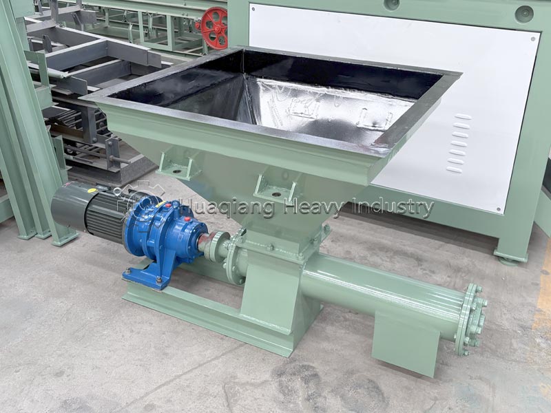
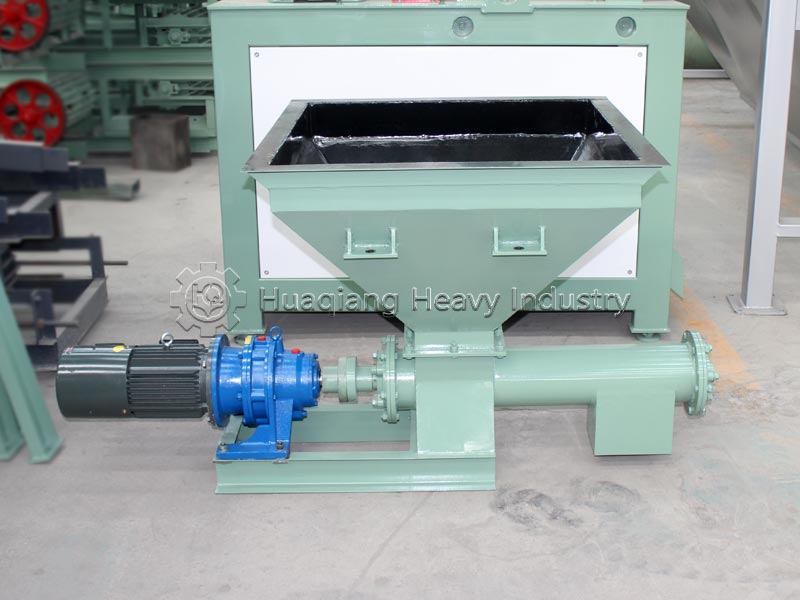
Equipment Introduction
Screw conveyors are closed, continuous conveying equipment without traction components. The industry mainstream models are divided into two main series: LS (shafted U-type/tubular) and WLS (shaftless). They rely on rotating helical blades to push materials and are widely used in complete production lines for organic fertilizers and compound fertilizers. They are primarily used for short-distance closed transfer, quantitative feeding, and integrated mixing of powders and granules. Core Advantages (Suitable for the Fertilizer Industry)
1. Fully Enclosed and Dust-Free: U-shaped cover/tube-type sealed structure ensures no dust leakage during the conveying of fertilizers and manure powder, meeting environmental protection standards.
2. Compact Space and Flexible Layout: Can be arranged horizontally or at an angle of ≤20°, with multiple feeding and unloading points, suitable for batching silos and granulators for quantitative feeding.
3. Combines Conveying and Mixing Functions: Simultaneously mixes materials during conveying, eliminating the need for separate mixing equipment.
4. Low Cost and Small Footprint: Replaces belt conveyors for short-distance conveying, making it the preferred choice for small plant environments.
5. Variable Frequency Precision Material Control: Enables stable quantitative batching, making it a core feeding device in fertilizer batching processes.
Structural Composition
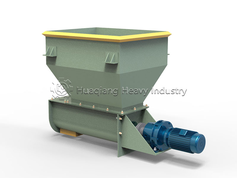
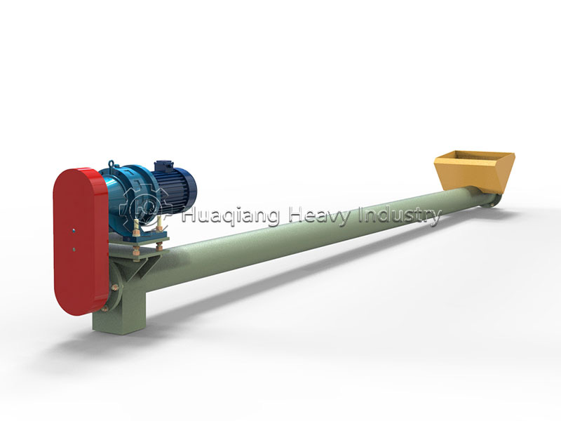
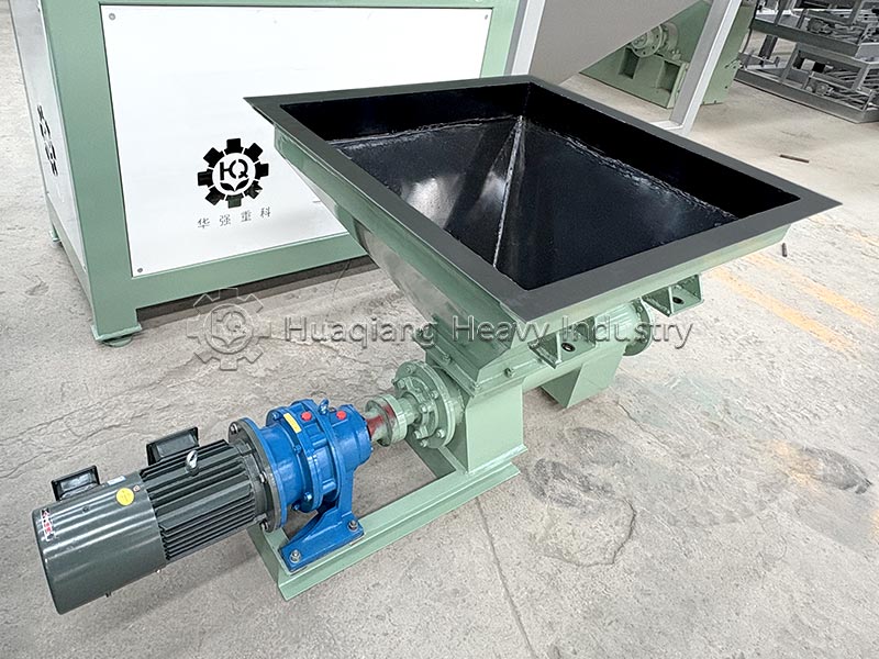
A complete screw conveyor typically consists of three main parts: the screw conveyor body, the inlet/outlet device, and the drive unit. The screw conveyor body is the core component, composed of a head section, an intermediate section, and a tail section.
Specifically, its main components include:
Screw (Auger): The main component for material conveying, consisting of screw blades and a screw shaft. Screw blades come in various types depending on the material, such as solid (full-surface) and ribbon-face. The screw shaft is usually made of hollow steel tubing with a diameter of 30–70 mm.
Bearings: Used to support the screw, and are classified into three types according to their location:
Head Bearing: Installed at the discharge end, bearing radial and axial forces, using a radial thrust bearing.
Tail Bearing: Installed at the inlet end, bearing only radial forces, using a radial spherical bearing.
Intermediate Hanger Bearing: When the screw shaft length exceeds 3 meters, it needs to be installed in the middle to prevent bending.
Material trough (casing): Usually made of thin steel plate, with a semi-circular bottom cross-section, used to hold the conveyed material.
Drive unit: Consists of an electric motor, reducer, and transmission components, providing power to the equipment.
Working Principle
The motor drives the screw shaft to rotate at a constant speed. Material falls into the machine casing from the feed inlet. The rotating screw blades generate axial thrust. Constrained by friction at the bottom of the trough, the material does not rotate with the blades circumferentially, but is propelled forward along the axial direction of the casing and continuously discharged from the discharge port.
1. Horizontal Conveying: Thrust directly pushes the material.
2. Inclined Upward Conveying: Relies on the blades to lift and counteract the downward force of the material; the larger the angle, the lower the conveying efficiency.
3. Shaftless Model: Flexible integral screw directly pushes the material, eliminating the obstruction of viscous wet materials by the absence of a hanging shaft, preventing entanglement and blockage.
Equipment applicable raw materials
| Classification | Material Type | Specific Materials | Supplementary Notes |
|---|---|---|---|
| Applicable Materials | Powdery | Cement, lime powder, talcum powder, flour, starch, coal powder, mineral powder | Loose powder with good flowability |
| Granular | Grain, sand, plastic pellets, fertilizer granules | Good granular flowability, not easy to caking | |
| Small‑lump | Small coal lumps, stones, mineral slag | Lump size shall be less than allowable passing dimension of equipment | |
| Special Materials | Low‑viscosity paste materials; sludge, domestic waste (shaft‑less screw) | Low‑viscosity paste requires special screw structure; shaft‑less model is preferred for sludge and winding materials | |
| Inapplicable Materials | High‑viscosity / easily‑caking sticky materials | High‑viscosity paste, easily‑caking sticky materials | Easy to adhere to screw blades and cause material accumulation & blockage |
| Large‑block Materials | Large‑size lump materials | Block flow channel, extremely prone to jamming | |
| Fragile Materials | Fragile and breakable materials | Screw conveying pressure may cause material crushing; model selection needs evaluation | |
| Working‑condition Temperature | Standard Model | ‑ | Material temperature < 200℃ |
| High‑temperature Resistant Model | ‑ | Max withstand temperature up to 400℃ |
Applications in Fertilizer Production Lines
Standard configuration for the three core sections of the entire production line: batching, granulation, and fine powder recovery:
1. Batching Section (Core Purpose): A screw feeder below the silo provides quantitative feeding, precisely proportioning various organic and chemical fertilizer powders, replacing manual feeding;
2. Granulation Feeding and Conveying: The discharge screw from the mixer feeds the material at a uniform speed into the disc/drum granulator, stabilizing the granulation feed flow;
3. Fine Powder Recycling: Fine powder generated during screening is returned to the mixer via a short screw for secondary granulation;
4. Coating Support: A powder coating agent (talc) is quantitatively conveyed to the inside of the coating machine;
5. Short-Distance Transfer: Small quantities of material are conveyed in a closed system between silos and at the front end of the drying process.
Supporting Process Link: Raw Material Silo → LS Screw Quantitative Batching → Mixer → LS Screw → Granulator → Dryer → Cooler → Screening Machine → Fine Powder Screw Return → Mixer
Operation and Maintenance
While screw conveyors are relatively easy to maintain, the following points directly impact equipment lifespan and operational stability:
1. Lubrication Management: Regularly lubricate bearings, gears, chains, and other transmission components.
2. Blade Inspection: Periodically check the wear of the screw blades. Repair or replace severely worn blades promptly.
3. Overloading Prohibited: Do not overload the conveying capacity; otherwise, material will not be able to discharge, leading to screw shaft bending and casing damage.
4. Temperature Monitoring: Under high-temperature conditions, ensure the casing expands and contracts freely to prevent thermal expansion and jamming.
5. Abnormal Handling: If a harsh noise is emitted during operation, immediately stop the machine for inspection, eliminating faults such as blade interference with the casing or bearing damage.
6. Shutdown Cleaning: After conveying viscous or easily agglomerated materials, clean the trough promptly to prevent residual material from hardening and causing jamming.
Summary of Equipment's Comprehensive Technical Features:
1. Enclosed and environmentally friendly, zero dust generation during powder conveying, suitable for environmental control measures in organic fertilizer plants;
2. Multi-functional, capable of conveying, batching, and light mixing, simplifying production line equipment configuration;
3. Minimal footprint, multi-point inlet and outlet design suitable for small batching workshops;
4. Precise quantitative control, variable frequency speed regulation achieves accurate fertilizer proportioning, improving the stability of nutrient content in the finished product;
5. Different models are available to handle dry and wet materials. The LS shafted model is suitable for dry powder materials, while the WLS shaftless model is suitable for high-moisture, sticky manure materials, covering the conveying needs of all fertilizer categories.
| Model | Screw Diameter | Rotation Speed | Capacity |
| LS160 | 160 | 112 | 3.2- |
| 90 | 7.8-2.6 | ||
| 71 | 6.2-2.1 | ||
| 56﹡﹡ | 4.9-1.6 | ||
| LS200 | 200 | 100 | 16.9-5.6 |
| 80 | 13.5-4.5 | ||
| 63 | 10.7-3.6 | ||
| 50﹡﹡ | 8.5-2.8 | ||
| LS250 | 250 | 90 | 29.9-9.9 |
| 71 | 23.5-7.8 | ||
| 56﹡﹡ | 18.5-6.2 | ||
| 45﹡﹡ | 14.9-5.0 | ||
| LS315 | 315 | 80 | 52.9-17.6 |
| 63 | 41.6-13.9 | ||
| 50﹡﹡ | 33.1-11.0 | ||
| 40﹡﹡ | 26.4-8.8 | ||
| LS400 | 400 | 71 | 85.3-28.2 |
| 56 | 67.3-22.4 | ||
| 45﹡﹡ | 54.1-18 | ||
| 36﹡﹡ | 43.2-14.4 |