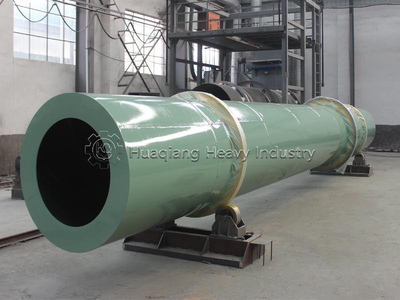
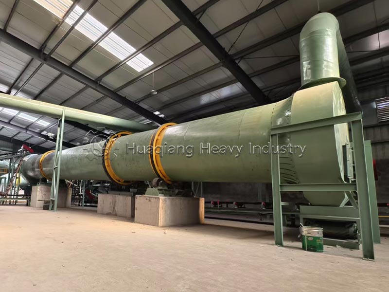
Equipment Introduction
Fertilizer rotary dryer machines are core post-processing equipment in fertilizer production lines. They are primarily used to dehydrate and dry wet materials after granulation or fermentation, reducing the moisture content of the finished product to a safe storage standard (typically ≤15%), preventing mold and clumping, while simultaneously improving granule hardness and appearance.
In the fertilizer industry, rotary drum dryers hold a dominant position. They employ a horizontal, inclined rotating drum design, using internal lifting plates to continuously tumble and toss the material, ensuring full contact with high-temperature hot air and achieving efficient heat and mass transfer. This equipment features large processing capacity, stable continuous operation, wide fuel adaptability, and high return on investment, and is widely used in the production of organic fertilizers, compound fertilizers (NPK), ammonium phosphate (MAP/DAP), ammonium sulfate, potash fertilizers, and various soil conditioners.
Structural Components of the Equipment
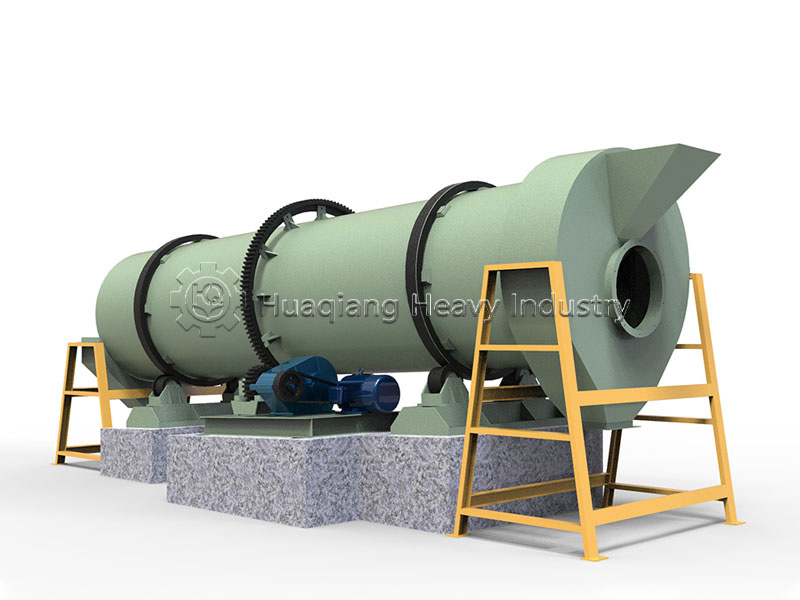
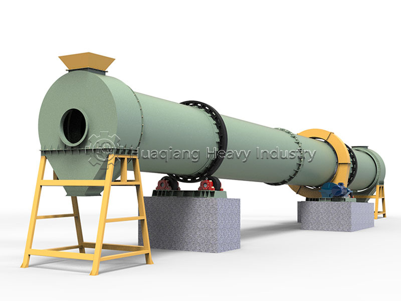
The fertilizer rotary drum dryer can be divided into five main components:
1. Drum Body (Machine Body)
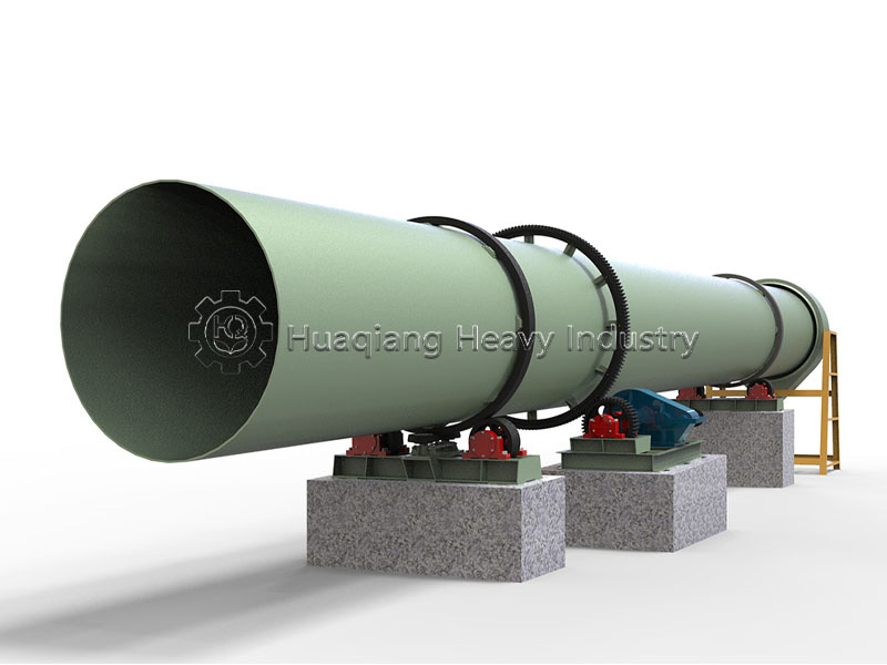
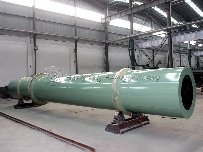
The drum body is the most important part of the entire dryer, welded from high-quality medium carbon steel plates. The dryer is a cylinder slightly inclined (usually 2-5 degrees) to the horizontal. Lifting plates (lifting plates) are installed on the inner wall of the drum, made of high-quality wear-resistant materials, with a reasonable distribution angle design. Their function is to continuously lift and scatter the material, ensuring full contact between the material and the hot airflow.
2. Support Frame and Support Section
The rotating parts of the entire machine body are supported by the support frame, which bears a significant load. The roller support frame is welded from medium carbon steel plates and channel steel. The rollers fixed to the frame are made of high-quality anti-corrosion and wear-resistant materials, greatly improving service life. The roller support frame adopts integrated casting technology, with lifting holes at the four corners for easy loading, unloading, and transportation. Key components include the front roller ring, rear roller ring, guide roller, and drag roller.
3. Transmission Section
The transmission section is the core that drives the entire machine. The transmission frame is welded from high-quality channel steel, and the main motor and reducer mounted on the transmission frame are both reliable products. The motor drives the pulley, V-belt, and reducer to transmit power to the transmission shaft. A small gear mounted on the transmission shaft meshes with a large gear ring fixed to the machine body, driving the machine to rotate.
4. Feeding, Discharging, and Sealing Devices
Feeding End: Equipped with a feeding hopper and feeding pipe; material is added from the higher end.
Discharging End: Equipped with a discharge port and a star-shaped discharge valve.
Sealing Ring: Ensures a tight system seal, preventing leakage of hot air and dust.
5. Auxiliary Equipment
A complete drying system also includes: a heat source device (coal, natural gas, steam, biomass pellets, etc.), a feeder, an induced draft fan, dust collection equipment (bag filter, cyclone dust collector, desulfurization scrubbing tower, etc.), and a power distribution cabinet.
Applicable Raw Materials for the Equipment
The fertilizer dryer is highly adaptable to various raw materials, including:
1. Organic Fertilizer Raw Materials
Various livestock and poultry manure (chicken manure, pig manure, cow manure, sheep manure, etc.)
Urban sludge, biogas residue, kitchen waste
Agricultural by-products and waste such as straw, forage, distiller's grains, medicinal residue, and fruit residue
2. Chemical Fertilizer Raw Materials
Compound fertilizer granules; blended fertilizer raw materials; phosphate fertilizer, ammonium sulfate, etc.
3. Moisture Content Adaptability
The organic fertilizer dryer can directly dry wet materials with a moisture content of 70%-80% to a safe storage moisture content of 13% in one pass. The moisture content of wet granules after compound fertilizer granulation is usually 25%-35%, which can be reduced to below 14% after treatment by a drum dryer.
4. Raw Material Handling Precautions
Materials usually need to be pre-treated before entering the dryer—controlling the initial moisture content ≤60% and breaking up the clumps using a crusher. The drying temperature needs to be controlled according to the heat sensitivity of the material to avoid nutrient volatilization or organic matter carbonization caused by high temperature.
Working Principle of the Equipment
The working principle of the fertilizer drum dryer is based on the principles of heat conduction and convection heat transfer:
1. Material Feeding and Conveying
Wet materials are fed into the hopper by a belt conveyor or bucket elevator, and then fed into the feed end of the drum through a feeding pipe. The inclination of the feeding pipe must be greater than the natural angle of repose of the material to ensure smooth flow.
2. Hot Air Supply
High-temperature flue gas generated by the hot air furnace enters the drum under the suction of the fan. Depending on the drying characteristics of the material, the high-temperature flue gas can enter the drum in the same direction as the material (parallel flow) or in the opposite direction (reverse flow).
3. Material Turning and Drying
As the drum rotates, lifting plates installed on the inner wall of the drum continuously lift and evenly distribute the material. The material is constantly turned, lifted, and scattered inside the drum, making full contact with the high-temperature hot air. Moisture continuously absorbs heat and turns into water vapor, which is discharged from the drum through the dust collector system with the flue gas. 4. Material Feeding and Discharge
Due to the inclined installation of the drum (2-5 degrees), the material gradually moves towards the drum outlet under the influence of gravity and during the scattering process. The dried material flows out from the discharge port and is discharged through a star-shaped discharge valve. With the continuous rotation of the motor and the continuous intake of material, large-scale continuous production is achieved.
5. Temperature Control
The inlet flue gas temperature is typically 600℃-800℃, the outlet exhaust gas temperature is 80℃-120℃, and the material contact temperature does not exceed 50℃. The intelligent temperature control system monitors and adjusts the heat source input in real time through temperature sensors and a PLC control system to ensure temperature fluctuations are ≤±10℃.
Applications of the equipment
Fertilizer dryers have a very wide range of applications:
| Application Field | Typical Materials |
|---|---|
| Organic Fertilizer | Livestock and poultry manure, chicken manure, cow dung, sheep manure, sludge, biogas residue, straw powder, kitchen waste granules |
| Compound Fertilizer | NPK compound fertilizer, monoammonium phosphate (MAP), diammonium phosphate (DAP), triple superphosphate (TSP) |
| Inorganic Fertilizer | Ammonium sulfate, ammonium nitrate, potassium chloride, potassium sulfate, urea granules |
| Soil Conditioner | Gypsum powder, limestone powder, humic acid, biochar |
| Others | Feed raw materials, vinasse, pomace, mineral powder, ore |
Equipment Operation and Maintenance Methods
(I) Pre-start Preparation
1. Heat Source Check: Ignite the hot air furnace 30 minutes in advance and check the combustion chamber, feeding device, and blower for normal operation.
2. Equipment Inspection: Clear any stuck material from the feed hopper; check the lubrication status of each bearing; confirm the grounding wire is in good condition.
3. No-load Test Run: New machines or machines after major overhauls need to run under no-load for 8 hours. The bearing temperature rise should be stable, and the termination temperature should not exceed 50°C; the gear noise should be uniform, with no abnormal vibration.
(II) Operation
1. Start-up Sequence: First, start the induced draft fan → start the blower → ignite the hot air furnace → after the temperature stabilizes, start the main motor → start the feeding equipment.
2. Parameter Monitoring: Monitor the cylinder rotation speed, hot air temperature (usually controlled between 150–400°C), discharge moisture content, and motor current in real time. 3. Shutdown sequence: Stop feeding → Stop the main unit after the material in the cylinder is emptied → Stop the hot blast furnace after 30 minutes → Finally, stop the induced draft fan.
(III) Daily Maintenance
| Maintenance Part | Maintenance Cycle | Maintenance Content |
|---|---|---|
| Gear Meshing Surface | Every shift | Apply grease for lubrication |
| Riding‑ring Surface | Every 7 days | Apply grease once |
| Bearing Housing | Every 3 months | Fill or replace grease |
| Reducer | Before first use / Every 4 months | Fill or replace gear oil |
| V‑belt | Monthly inspection | Check tension and wear condition |
| Lifting plate / Gear ring | Quarterly | Check wear, deformation and fastening status |
Equipment Application in Production Lines
1. Core Position in Organic Fertilizer Production Lines
The rotary drum dryer connects granulation and finished product packaging in organic fertilizer production lines, serving as a crucial process. The moisture content of wet granules after granulation is typically 25%-35%. After treatment with the rotary drum dryer, the moisture content can be reduced to below 14%, directly affecting the storage stability and commercial value of the granules.
Complete Processing Flow:
Raw Material Pretreatment → Fermentation and Composting → Crushing → Batching and Mixing → Granulation → Rotary Drum Drying → Cooling → Screening → Packaging
2. Use in conjunction with a Cooler
Because the temperature of the dried granules is relatively high (typically 60℃-80℃), direct storage is not advisable. Therefore, the dryer is usually used in conjunction with a cooler. After drying, the material enters the cooler for cooling before screening and packaging.
3. Automated Control
Modern fertilizer drying production lines are typically equipped with intelligent temperature control systems. Temperature sensors and a PLC control system monitor and adjust the heat source input in real time. A quantitative feeding device is also configured, linked with hot air temperature and drum rotation speed for integrated control.
4. Supporting Equipment
A complete drying system requires the following supporting equipment:
Heat Source: Coal-fired hot air furnace, gas-fired hot air furnace, biomass hot air furnace, etc.
Feeding and Loading Equipment: Belt conveyor, bucket elevator, screw feeder
Exhaust Fan and Dust Removal Equipment: Bag filter, cyclone dust collector, desulfurization scrubbing tower, etc.
Unloading Device: Rotary rotary valve
5. Capacity Adaptability
The fertilizer dryer is suitable for organic fertilizer and compound fertilizer production lines with an annual output of 10,000 to 500,000 tons. The equipment design takes into account production margins, so even if the output increases slightly, there is no need to replace the equipment.
Common Faults, Causes, and Standardized Solutions
| Fault Phenomenon | Root Cause | Professional Solutions |
|---|---|---|
| Undried material, high moisture content of discharged product | Insufficient hot air supply; excessive feeding rate; too fast cylinder rotation speed; lifting plate falling off | 1. Raise hot blast stove temperature; 2. Reduce feeding speed; 3. Lower cylinder rotation speed; 4. Stop machine for maintenance, repair weld or replace lifting plates |
| Riding‑ring deviation, axial drift | Loose riding‑ring joint; uneven force on supporting rollers | 1. Tighten concave joint of riding‑ring; 2. Adjust supporting roller height evenly with shims, avoid cylinder vibration caused by over‑tightening |
| Cylinder lateral shifting, severe vibration | Severe wear of supporting rollers and thrust rollers; loose anchor bolts of supporting roller base | 1. Grind, repair or replace supporting rollers and thrust rollers; 2. Calibrate supporting roller level, tighten all lock nuts |
| Abnormal gear meshing noise, misalignment | Single‑side wear of pinion; loose connection between big gear ring and cylinder | 1. Reverse pinion for reuse; replace directly if both sides are worn; 2. Align flange connection between big gear ring and cylinder, tighten bolts |
| Large vibration during cylinder operation | Broken connection between supporting roller assembly and base, loose bolts; uneven side wear of riding‑ring | 1. Correct supporting roller installation position, tighten anchor bolts; 2. Machine repair riding‑ring side surface or replace riding‑ring |
| Material backflow at feed inlet, dust overflow | Insufficient induced draft fan air volume; aging and air leakage of end seals | 1. Inspect fan, adjust air damper to increase negative pressure; 2. Replace flexible sealing parts at feeding and discharging ends |
| Bearing temperature >50℃ (8‑hour no‑load test standard) | Lack of lubricating grease; internal bearing wear | Stop machine and add lubricating grease; replace bearing directly if wear is severe |
Target Customers for Fertilizer Dryers:
1. Organic Fertilizer Manufacturers: Manufacturers using livestock manure and agricultural waste as raw materials to produce commercial organic fertilizers.
2. Compound (Mixed) Fertilizer Plants: Enterprises producing inorganic or organic-inorganic compound fertilizers such as NPK, ammonium phosphate, and ammonium sulfate.
3. Large-Scale Livestock Farms: Enterprises with their own manure treatment centers that need to convert manure into organic fertilizer or fuel pellets.
4. Sludge Treatment and Environmental Protection Companies: Projects involving the drying and resource utilization of municipal sludge and industrial organic sludge.
5. Biomass Energy Enterprises: Enterprises that dry distiller's grains, medicinal residues, and straw to produce biomass fuel or feed.
6. Soil Remediation and Conditioner Manufacturers: Manufacturers of soil conditioners such as gypsum, limestone, and humic acid.
| Model | Inner Diameter (mm) |
Shell Length (mm) |
Inclination (°) |
Rotation Speed (r/min) |
Production Capacity (t/h) |
Hot Air Inlet Temp (°C) |
Hot Air Outlet Temp (°C) |
Motor Model | Motor Power (kW) |
Motor Rotation Speed (r/min) |
Reducer Model |
|---|---|---|---|---|---|---|---|---|---|---|---|
| ZG12120 | 1200 | 12000 | 2‑5 | 4.7 | 2‑2.5 | 150‑250 | 60‑80 | Y160M‑4 | 7.5 | 1460 | ZQ350 |
| ZG15120 | 1500 | 12000 | 2‑5 | 5.0 | 4‑6 | 150‑250 | 60‑80 | Y160L‑4 | 15 | 1440 | ZQ400 |
| ZG15150 | 1500 | 15000 | 2‑5 | 5.0 | 5‑7 | 150‑250 | 60‑80 | Y160L‑4 | 15 | 1440 | ZQ500 |
| ZG18150 | 1800 | 15000 | 2‑5 | 3.9 | 7‑10 | 150‑250 | 60‑80 | Y200L1‑6 | 18.5 | 970 | ZQ500 |
| ZG20200 | 2000 | 20000 | 2‑5 | 3.9 | 8‑14 | 150‑250 | 60‑80 | Y200L2‑6 | 22 | 970 | ZQ650 |
| ZG22220 | 2200 | 22000 | 2‑5 | 3.2 | 12‑16 | 150‑250 | 60‑80 | Y250M‑6 | 37 | 980 | ZQ750 |
| ZG24240 | 2200 | 24000 | 2‑5 | 3.0 | 14‑19 | 150‑250 | 60‑80 | Y280S‑6 | 45 | 970 | ZQ850 |