Equipment Introduction
The hydraulic trough-type compost turner, also known as a hydraulic lifting trough-type compost turner or hydraulic trough-type turning machine, is a core automated piece of equipment for realizing the trough-type aerobic fermentation process in large-scale organic fertilizer production, livestock and poultry manure treatment, and municipal sludge resource utilization projects. Based on the traditional trough-type compost turner, this equipment introduces a fully hydraulic drive and control system. Relying on hydraulic transmission technology, it integrates the core advantages of strong power, efficient turning, stability, durability, and intelligent convenience, enabling all-round turning and oxygen supply of materials within the fermentation tank, significantly shortening the fermentation cycle.
Unlike the inefficient operation mode relying on manual turning or small compost turners, the hydraulic trough-type compost turner can achieve continuous and deep turning operations within the fermentation tank. It can quickly replace oxygen in the pile, evaporate excess moisture, and crush and evenly mix materials. It is a key piece of equipment for the harmless treatment of livestock and poultry manure, kitchen waste, and agricultural waste. Its application marks a leap from "extensive manual labor" to "factory-scale intelligent control" in organic fertilizer fermentation.
Equipment Structure
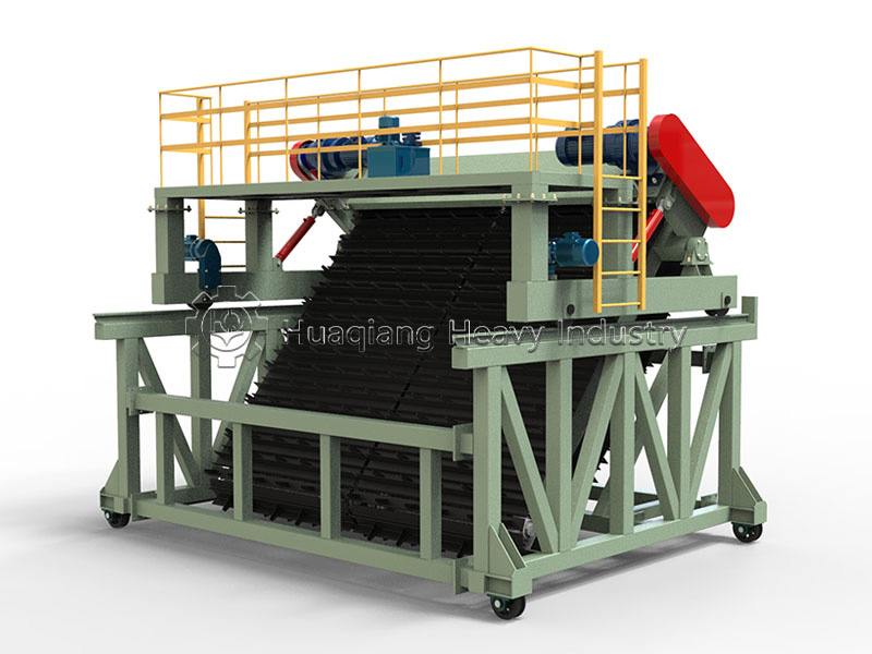
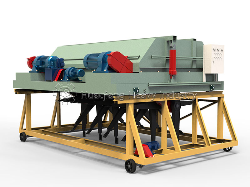
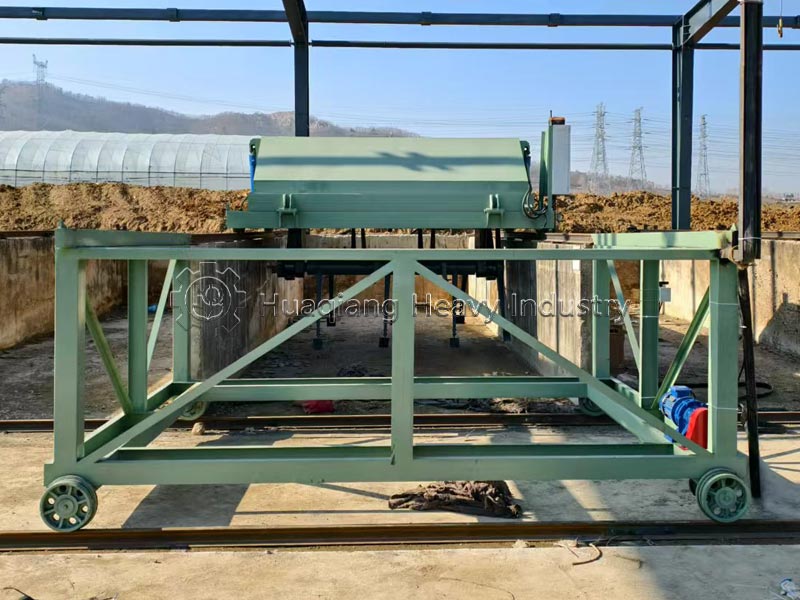
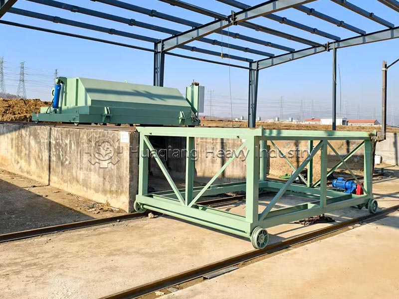
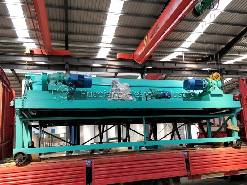
The hydraulic trough-type compost turner consists of six core functional modules + an electrical control safety system + a matching moving trolley. Unlike ordinary models, its core component is an independent hydraulic lifting unit:
1. Power Transmission Device (Turning Drum Rotation Power)
Composed of dual main drive motors, a cycloidal pinwheel reducer, a transmission sprocket, heavy-duty bearing seats, and the drum main shaft; the reducer is filled with No. 50 special machine oil to provide stable rotational torque for the turning drum. The drum propeller blades synchronously complete the material crushing and horizontal pushing (single pushing distance 0.2~1m).
2. Track Walking Device
Composed of a walking motor, transmission chain, transmission shaft, track walking wheels, and a walking chassis frame; the equipment travels back and forth along concrete tracks on both sides of the fermentation tank. The tracks must be grounded to ensure electrical safety.
3. Hydraulic Lifting System (Core Differentiating Component of this Equipment) The entire hydraulic unit is independently equipped and consists of a hydraulic pump motor, high-pressure hydraulic pump station, electromagnetic reversing valve assembly, high-pressure oil-resistant hydraulic oil pipes, lifting hydraulic cylinders, and lifting support arms. The cylinder extension and retraction are controlled by an electronically controlled valve assembly, achieving overall lifting/lowering of the turning drum. No manual adjustment of the winch chain is required, and the lifting action is smooth and without jamming.
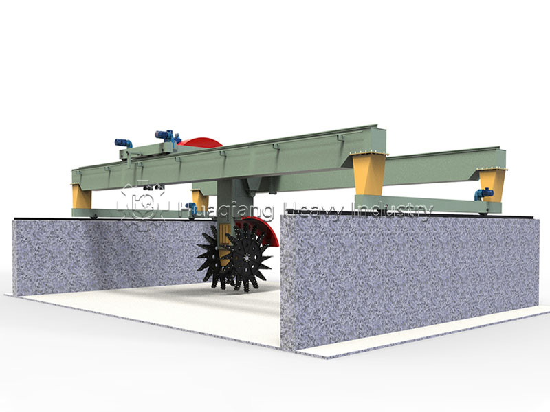
4. Turning Drum Assembly (Core Working Component) Composed of support arms, turning drum, and spirally arranged wear-resistant alloy shovels (rake teeth). The alloy shovels have high hardness, wear resistance, and corrosion resistance, effectively breaking up clumps of manure and turning the bottom anaerobic material to the surface for full air contact, simultaneously propelling the material towards the discharge end of the fermentation tank at a uniform speed.
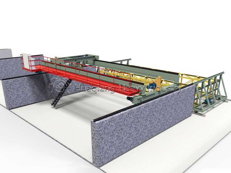
5. Transfer Vehicle (Optional Equipment) Composed of an independent walking motor, transmission gears, and load-bearing wheels. It carries the turning machine laterally to other fermentation tanks, enabling multi-tank production with one machine and reducing overall equipment investment.
6. Electrical Control Safety System: Integrates a PLC centralized control cabinet, soft starter (reduces the impact load of motor starting), limit switches at both ends of the track, grounding protection circuit for the whole machine, and pressure protection valve for the hydraulic system; limit switches enable automatic reversing and stopping, hydraulic relief valve prevents cylinder overpressure damage, and multiple electrical protections prevent equipment derailment and overload failure.
Raw Materials for the Equipment
The hydraulic trough compost turner primarily processes various organic wastes, including but not limited to:
1. Livestock waste: chicken manure, pig manure, cow manure, sheep manure, and other livestock and poultry manure
2. Municipal waste: urban sludge, sewage sludge
3. Agricultural processing waste: sugar mill filter mud, residue cake
4. Agricultural waste: straw, sawdust
5. Kitchen waste: kitchen garbage
The raw materials typically possess characteristics such as high moisture content, high viscosity, presence of sand and fiber, and strong corrosiveness. To address these characteristics, the hydraulic trough compost turner has undergone significant reinforcement in terms of materials and anti-clogging design.
Working Principle of the Equipment
The core working principle of the hydraulic trough-type compost turner lies in "hydraulic drive + synergistic turning":
1. Basic Workflow
Organic materials are piled in the fermentation trough, and the turner moves along the trough via a walking mechanism. During operation, the equipment moves at a constant speed along the track laid on the side wall of the fermentation trough, while a high-power hydraulic motor drives the turning rotor to rotate at high speed.
2. Turning and Oxygenation Process
The spirally arranged alloy stirring teeth (or staggered wear-resistant alloy steel rake teeth) on the rotor cut into the deep layers of the material, breaking up and throwing up the hardened material, allowing it to fully contact the air. The material is turned over and stirred, moving backward 0.2-1 meter. The turning trolley turns laterally to one side and stops after touching the limit switch. After the entire machine travels longitudinally for 3-5 seconds (approximately 250-300 mm), the turning trolley begins to turn laterally to the other side, repeating this back-and-forth operation to achieve the effects of turning and oxygenation.
3. Hydraulic System Working Principle
The high-pressure hydraulic pump serves as the power source, transmitting power through hydraulic oil to drive the turning gear shaft and the traveling mechanism in coordinated operation. The hydraulic system boasts high torque and rapid response, with a turning force typically 1.5-2 times that of ordinary models. During operation, the high-pressure hydraulic pump drives the turning gear shaft and the traveling mechanism in coordinated operation.
4. Deep Turning Effect
The hydraulic lifting device can adjust the rotor position in real time according to the pile height, ensuring consistent turning depth. This deep turning mode brings the oxygen-deficient "cold material" to the surface, burying the dry "hot material" at the surface. Combined with the ventilation system at the bottom of the trough, the pile temperature rapidly rises to over 70°C within 48 hours, thoroughly killing pathogens, insect eggs, and weed seeds.
Equipment Operation Method
Pre-start Inspection: Check all lubrication points, hydraulic oil levels, and electrical connections for proper functioning.
Positioning: Use the transfer cart to align the equipment with the target fermentation tank.
Hydraulic Lowering: Activate the hydraulic system to lower the turning drum to the material depth.
Start Operation: Start the rotary motor, followed by the travel motor to begin turning.
Cyclic Operation: After turning to the end of the tank, raise the drum, and the equipment can quickly retract or be switched using the transfer cart.
Equipment Maintenance Methods:
Lubrication: Check bearing and hydraulic rod lubrication every shift, and change gear oil in the reducer regularly.
Cutter Inspection: The feed teeth are wear parts; replace them promptly if severe wear is found to ensure optimal turning and threshing effect.
Hydraulic System: Regularly check the oil lines for leaks and keep the hydraulic oil clean.
Corrosion Prevention: The fermentation environment is corrosive; clean the machine body regularly and apply anti-corrosion paint as needed.
Common Equipment Problems and Solutions
| Fault Category | Fault Phenomenon | Fault Causes | Standard Treatment Solutions |
|---|---|---|---|
| General Compost Turning Fault | Difficult compost turning, roller overload jamming, loud operating noise of main motor | 1. Material accumulation thickness exceeds rated turning depth 2. Alloy rake teeth/main shaft deformed; straw/ropes wound around roller 3. Foreign objects jammed in gears or gear tooth surface damaged |
1. Shovel excess fertilizer to reduce material height 2. Power off, calibrate deformed parts, remove wrapped foreign objects, replace severely worn rake teeth 3. Clear gear foreign objects; replace full gear set if damaged |
| Unstable machine traveling, abnormal noise of traveling reducer, overheated machine body | 1. Caked materials jammed in sprockets and wheels 2. Bent transmission shaft, elongated slack chains 3. Lack of special lubricating oil for reducer and bearings |
1. Shut down and clean accumulated materials of traveling mechanism 2. Calibrate or replace deformed transmission shaft; adjust/replace chains 3. Inject No.50 reducer oil and molybdenum disulfide grease |
|
| Severe wear & deformation of roller rake teeth, uneven material turning, slow fermentation temperature rise | 1. Long-term operation leads to rake teeth wear & deformation 2. Offset angle of cutter shaft |
1. Replace rake teeth in groups when wear exceeds 1/3 original length 2. Adjust cutter shaft angle to keep left and right horizontal consistent |
|
| Overheating of reducer and bearings due to oil shortage, loose transmission chains and tooth skipping | 1. Insufficient lubricating oil 2. Elongated worn chains |
1. Fill lubricating oil and grease regularly 2. Adjust chain tension, replace excessively worn chains |
|
| Hydraulic System Exclusive Fault (FPY Model) | Slow & weak roller lifting, automatic cylinder sliding down, pressure holding failure | 1. Aging cylinder sealing parts cause internal leakage 2. Hydraulic pipeline leakage 3. Damaged pressure relief valve leads to pressure relief |
1. Disassemble cylinder and replace all oil seals 2. Tighten leaking joints, replace damaged oil pipes 3. Overhaul or replace pressure relief valve |
| Hydraulic pipeline & cylinder seal oil leakage, rapid drop of oil tank liquid level | 1. Aging & cracked high-pressure oil pipes 2. Damaged cylinder end cover gaskets 3. Loose valve group joints |
1. Replace aging high-pressure oil pipes 2. Replace cylinder sealing gaskets 3. Tighten all hydraulic pipeline joints |
|
| Abnormal pump station noise, excessive oil temperature rise, emulsified white hydraulic oil | 1. Blocked hydraulic filter causes insufficient oil supply 2. Cooling fan failure 3. Air/water vapor mixed into oil circuit |
1. Replace brand-new hydraulic filter element 2. Overhaul cooling fan, fully exhaust air from oil circuit 3. Drain emulsified oil, clean tank, fill new 46# anti-wear hydraulic oil |
|
| Solenoid valve spool jamming; roller only lifts or only descends | Impurities in hydraulic oil block valve spool | 1. Disassemble solenoid valve and clean spool impurities 2. Filter hydraulic oil and replace filter element simultaneously |
|
| Large hydraulic system pressure fluctuation, machine jitter & crawling during lifting | Air mixed into oil circuit; poor sealing causes air suction; pump & valve wear | 1. Exhaust whole system, inspect and replace sealing parts 2. Contact professional staff to overhaul hydraulic pump and valve group |
|
| Travel & Electrical System Fault | Machine traveling deviation, limit switch failure, unable to auto reverse & stop | 1. Uneven track settlement 2. Inconsistent tension of bilateral traveling chains 3. Limit switch circuit open circuit, oxidized contacts |
1. Calibrate track flatness 2. Adjust bilateral traveling chain tension to be consistent 3. Overhaul limit switch circuit, replace damaged switches |
| Frequent contactor burnout in control cabinet, circuit phase loss, joint short circuit | 1. Mismatched or aging contactor model 2. Damaged circuit insulation, loose wiring terminals |
1. Replace qualified contactors of the same model 2. Overhaul power lines, tighten terminals, troubleshoot phase loss faults |
|
| Machine grounding failure, electric leakage safety hazard | Disconnected grounding wire, excessive grounding resistance | 1. Inspect and repair grounding wire 2. Test grounding resistance to meet safety standards |
|
| Motor Startup Fault | Main motor & hydraulic pump motor hard to start or fail to start, buzzing abnormal startup noise | 1. Severely worn or damaged motor internal bearings 2. Bent reducer reduction shaft, excessive load 3. Low supply voltage, unbalanced three phases, phase loss |
1. Disassemble motor end cover and replace new bearings 2. Disassemble reducer, calibrate or replace reduction shaft 3. Overhaul power lines, restart machine only after voltage recovers to rated 380V and three-phase balance |
| Motor overheating protection shutdown after short running time | 1. Material overload causes excessive load 2. Poor motor heat dissipation 3. Worn bearings lead to large operating resistance |
1. Reduce material thickness to lower turning load 2. Clean dust on motor cooling fins to improve ventilation 3. Inspect and replace worn bearings |
Application of the Equipment in the Production Line
The hydraulic trough compost turner is a widely used piece of equipment in organic fertilizer production lines. Located between solid-liquid separation and aging screening, it is the "main battlefield" for biochemical reactions.
1. Positioning in the Production Line
In the entire organic fertilizer production line, the hydraulic trough compost turner plays a core role in turning and disposing of materials. The equipment adopts a modular structure design, making installation convenient and allowing for rapid integration into large-scale organic fertilizer production lines. It can seamlessly connect to equipment such as crushers, mixers, and granulators, achieving integrated operations of organic raw material crushing, mixing, turning, and composting.
2. One Machine, Multiple Troughs Operation
With the aid of a transfer vehicle (shifting machine), "one machine, multiple troughs" can be operated in rotation, greatly improving equipment utilization and saving on infrastructure and equipment investment costs. For organic fertilizer projects with an annual production capacity of tens of thousands of tons or more, multiple troughs can be connected in parallel with one compost turner to achieve continuous feeding and discharging, significantly improving site utilization and production continuity.
3. Value in the Production Process: Stable turning and turning quality provides high-quality raw materials with suitable moisture content and uniform fineness for subsequent crushing and granulation processes, significantly reducing recycle rate and energy consumption. The equipment often integrates a biological deodorizing spray system, simultaneously spraying deodorizing bacteria during the turning and turning process to inhibit the volatilization of ammonia and hydrogen sulfide at the source, improving the factory environment.
Fermentation process of equipment
Hydraulic trough compost turner is the core equipment for realizing aerobic compost fermentation.
1. Principle of aerobic fermentation
The equipment uses aerobic compost turning and throwing technology to achieve aerobic fermentation of materials through turning and throwing. The turning process plays a decisive role in regulating temperature, moisture and oxygen content in the aerobic composting process.
2. Fermentation process control
Warming period (1-3 days): Toss slowly to avoid temperature loss and help activate microorganisms. Turning depth 60-80cm, walking speed 3-4m/min, 1-2 times a day
High temperature period (4-8 days): deep turning, sufficient oxygen supply, and controlled temperature ≤65℃. Turning depth 80-120cm, walking speed 2-3m/min, 2-3 times a day
Cooling period (9-12 days): Shallow tossing to reduce energy consumption and maintain decomposition. Turning depth 60-80cm, walking speed 3-5m/min, once a day
3. Fermentation effect
Through the deep turning mode, the temperature of the pile can quickly rise to above 70°C within 48 hours, completely killing pathogenic bacteria, insect eggs and weed seeds. The stacking temperature is stabilized in the optimal decomposition range of 55-65°C to accelerate microbial activity. The fermentation cycle is greatly shortened to 7-20 days (traditional fermentation takes more than 30 days).
4. Fermentation tank configuration
Build two fermentation tanks with a height of 1.5-1.8 meters, a length of 60-80 meters, and a distance of 3-10 meters between the two walls, and set up light rails on the walls. A flipping machine that can move forward, backward, left and right, and up and down is installed on the track. Fresh livestock and poultry manure enters the trough from one side and is continuously turned by the compost turner to form decomposed organic fertilizer on the other side of the trough.
Equipment demand groups
1. Large-scale livestock and poultry breeding group / large-scale breeding farm: 10,000-head pig farm, 100,000-feather chicken farm, 1,000-head cattle and sheep breeding base, self-built manure resource organic fertilizer workshop, on-site consumption of breeding manure, achieving breeding cycle and environmental protection standards.
2. Professional commercial organic fertilizer and bio-fertilizer manufacturers, large-scale organic fertilizer processing plants and bio-fertilizer technology companies, build standardized tank fermentation workshops to produce powdered and granular commercial organic fertilizers for external sales.
3. Municipal environmental protection solid waste disposal units: urban sewage treatment plants, sanitation garden waste treatment stations, and kitchen waste resource disposal centers, dispose of municipal sludge, garden dead branches, and organic kitchen slurry to achieve solid waste reduction and harmlessness.
4. Agricultural products deep processing factories: sugar factories, liquor/beer brewing factories, traditional Chinese medicine pharmaceutical factories, and oil pressing factories, which process the by-products of sugar slurry, distiller's grains, medicinal residues, and pressed oil cakes, and use the by-products to make fertilizers.
5. Large-scale planting bases, modern agricultural industrial parks, horticultural flower farms, thousands of acres of fruit and vegetable planting bases, nursery stock and flower nurseries, and facility agricultural industrial parks, self-made organic cultivation substrates and base fertilizers, reducing the use of chemical fertilizers for planting and improving the quality of agricultural products.
6. Large-scale edible fungi cultivation factory: A factory-based cultivation enterprise for Agaricus bisporus, Lentinus edodes, and Pleurotus ostreatus. Special equipment for the pre-fermentation and composting sections of cultivation materials ensures that edible fungi cultivation materials are fully decomposed and increases mushroom yield.
7. Environmental protection equipment complete set engineering provider, organic fertilizer production line integration service provider. Equipment integration and engineering installation enterprise undertaking complete organic fertilizer line projects, environmental protection treatment projects of breeding manure, and municipal solid waste disposal projects. FPY hydraulic models are sold as supporting complete lines of high-end fermentation equipment.
Summary of Equipment Advantages
Compared to traditional mechanical compost turners, hydraulic trough turners offer the following significant advantages:
1. Powerful Performance: The hydraulic system boasts high torque and rapid response, delivering 1.5-2 times the turning force of ordinary models, easily crushing high-moisture, high-viscosity, and large-lump organic materials.
2. Flexible Adjustment: The hydraulic system enables stepless lifting of the drum and smooth adjustment of the travel speed.
3. Deep Turning: Turning depth can reach up to 2.5 meters, eliminating dead zones.
4. High Automation: Equipped with a PLC control cabinet or wireless remote control, enabling fully automatic cyclic operation.
5. Energy Efficient: Energy consumption per ton is 20% lower than traditional equipment, and the fermentation cycle is shortened by more than 30%.
6. Strong Adaptability: One machine can operate in multiple troughs, significantly improving equipment utilization.
7. Robust and Durable: Key components are made of wear-resistant alloy materials, with a service life 2-3 times that of ordinary turning teeth.
| Hydraulic Lifting Compost Turning Machine | ||||
| Model | Main Motor | Walking Motor | Moving Motor | Hydraulic Pump Motor |
| FPY4 | 22kw | 1.5kw | 1.1kw | 4kw |
| FPY5 | 30kw | 1.5kw | 1.5kw | 4kw |
| FPY6 | 37kw | 2.2kw | 1.5kw | 4kw |